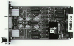
VME503

VME503 Highlights
- 4 Analog Output Channels
- 12 Bit D/A Resolution
- Optional 4-20 mA Outputs
- Single +5V Power Requirement
Overview
The VME503 12 bit Analog Output Card uses four 12 bit D/A converters to provide independently programmed voltage output channels. In addition, two channels can be configured for 4-20mA outputs by using optional voltage to current converters which install on the board.
Analog signal connections are made using reliable socket and header connectors which enables flat ribbon cable to be combined with gas tight and corrosion resistant connectors. An optional screw termination panel is also offered for simple and convenient field wire connections.
The VME503 card is a single height {3U, 100 x 160 mm} VMEbus card, requires +5 V power only, and has an operating temperature range of 0 to +70°C.
Optional Signal Conditioning
For low-level analog signal conditioning such as in sensor-based applications, Analog Devices 3B and 5B Series Signal Conditioning I/O subsystems offer rail-mounted industrial hardened analog signal interface modules with a single channel format and high level analog output. Optional sensor signal conditioning, transformer isolation of ±1500 V, high common-mode and normal-mode noise rejection makes the 3B series and 5B series ideal for analog output signal conditioning for the VME503.
Operation
The VME503 is used to take a digital word from the microcomputer and convert it into an analog signal (voltage or current). The design consists of digital registers which store the 12 bit digital words, four independent 12 bit D/A converters, two optional 4-20 mA converters and associated logic to interface to the VMEbus.
Digital/Analog Converter (D/A)
The VME503 contains four independent CMOS 12 bit D/A converters (AD7541). Each D/A output can be independently selected. The user has four output voltage ranges from which to jumper select. The 12 bits of resolution provide least significant bit values to 1.22 mV for a 0 to +5 V output range.
Current Output (V/I)
It is often desirable to transmit an analog signal as a current rather than a voltage since noise and IR drops in the cable and connectors will not degrade the accuracy of a current signal. Two of the four voltage outputs can be converted to a 4-20mA current loop output. These voltage-to-current modules meet all requirements of the ISA-S50.1 Standard for Type 3, Class L, non-isolated 4-20mA current loop transmitters which makes them ideal for use in process control applications. A user supplied +16V to +30V supply is required to power this loop.
The VMEbus +5V supply is all that is required to power the VME503 card. The on-board dc/dc converter is supplied with each card to convert the +5V supply to a low noise, isolated ±15V supply required by the analog circuitry.
VMEbus Interface
The VME503 is treated as a DTB slave module that responds to the address modifier lines and maps into the VMEbus short I/O address space. The address of the board is jumper selectable so that it can be mapped in any one of 256 positions with a VMEbus short I/O base address of JJ00 where JJ is the hexadecimal equivalent of the jumper selection.
The control logic generates 4 individual data strobes such that a write operation to one of the four D/A output word locations will generate a properly timed WRITE strobe to the correct register
Specifications
- Typical @ 25°C with nominal supply voltage unless otherwise noted
- Number of D/A Channels 4
- D/A Resolution 12 bits (4096 counts)
- D/A Input Codes Binary, Offset Binary
- Output Voltage Range 0 to +5V, 0 to +10V, ±5V, ±10V @5mA
- Output Current Range 4-20mA using 2 V/I converters (Optional, 2 channels only)
- Analog Connector 26 pin
- Non-linearly ±1/2LSB
- Differential Non-linearly ±1/2LSB
- Output Settling Time 25ms(to ±1/2LSB)
- Gain Error ±0.01% of FSR (Adjustable to Zero)
- Offset Error ±0.02% of FSR (Adjustable to Zero)
- Temperature Coefficient
- Gain ±15ppm/°C of FSR
- Offset ±25mV/°C
- Power Requirements +5V ±5% @ 550mA typ. 650mA max
- Temperature
- Operating 0 to 70°C
- Storage -55°C to +85°C
- Relative Humidity Meets or exceeds MIL-STD 202, Method 103
