
VME722
VME722 Highlights
- 3U VMEbus Rev C.1 Digital I/O Card
- VMEbus A16:D16 Short I/O Slave
- Eight Input, 7 Level VMEbus Interrupter
- 96 TTL Digital I/O Bits
- Independent Bit by Bit I/O Control
- 24 mA TTL Open Collector Drivers
- Each I/O bit Includes 4.7K Pull Up
- Four Digital I/O Channels
- 24 TTL Digital I/O Bits
- Channel Control Register
- Three 8 bit Input Buffers, Two Registers
- Three 8 bit Output Registers
- Two/Four Interrupt Inputs
- Software controlled +5 Volt Supply
- Board Control
- Board Control and Status Register
- IDR EPROM Identity Register
- 8259A Priority Interrupt Controller
- Reset to Disable/Safe State
- Diagnostic LEDs
- System, Software, and Application Support
- 50 Way Standard Ribbon Cable Out
- Direct I/F to Solid State Relay Rack (OPTO-22)
- Channel Monitor and Debug Tools
- Software I/O Library and Examples
VME722 Overall Functions
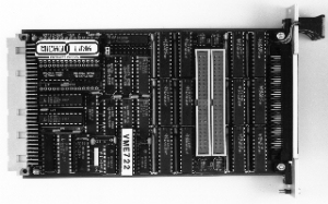
The Micro-Link VME722 digital I/O card combines high density TTL digital I/O capability with operational flexibility in a compact package. The VME722 is designed as a digital interface in industrial and embedded equipment control, but it is also suitable for parallel printer interfacing, etc.
Board operations and the programmers model divides into board level control functions and four independent I/O channels. The board control functions include an 8 bit Control and Status Register (CSR), EPROM based Identity Register (IDR), and a Priority Interrupt Controller (PIC). Each I/O channel includes a Channel Control Register (CCR) and data ports controlling 24 I/O bits.
The combination of board level and per channel control registers give the programmer a simple way to configure the interfaces and rapid access to disable a channel or the entire board should an emergency or hardware/software fault occur. Six front panel LEDs show board and channel status.
CSR (Control and Status Register)
CSR control bits include: Local Reset which resets all CCRs thus disabling outputs, Local SYSFAIL which drives the VMEbus SYSFAIL, S/U controls Supervisor/User or Supervisor only VMEbus access, ISEL selects which interrupt inputs are user by the PIC, and three bits (IL1-3) selects the VMEbus interrupt level. The CSR is read as a single byte, but each CSR bit is independently written. A VMEbus reset sets all CSR bits to zero, disabling all outputs and interrupts.
The IDR provides for automatic software configuration of the VME722. A 64 Kbytes EPROM is sequentially accessed through a single address. The EPROM may be used for board identification and revision information, and for driver or application storage.
PIC and VMEbus Interrupter
The PIC interrupt controller monitors 8 I/O signals, identifies the highest priority input, and generates a VMEbus interrupt on the selected level. When a VMEbus interrupt acknowledge is detected, the PIC returns a vector identifying the interrupt source. The PIC allows the programmer to select the vector base, level or edge triggered inputs, automatic or programmed end of interrupt service, fixed or rotating priorities, and to selectively mask each input. If interrupt level zero is programmed in the CSR, interrupts are disabled but the programmer can continue to use the PIC through its polling capability.
Digital I/O Channels
Each of the four channels is identically organized, with a CCR and 24 I/O bits interfaced through three 8 bit output registers, three input buffers, and two input registers. The CCR provides a global driver output control bit and a +5 Volt external supply switch. Both control bits are turned off by the CSR local reset bit, thus the channel is disabled by a VMEbus reset. Each I/O bit has a 4.7 KOhm pull up resistor to the switched +5 Volt supply. When the channel is reset, all I/O bits are therefore tri-stated and their pull-ups disabled.
The output registers are 24 mA open collector TTL drivers. In conjunction with the pull ups, the drivers will meet TTL or CMOS interface levels. Writing a one to any data bit in the register will turn on the output driver and presenting a logic low to the interface; writing a zero turns the driver off, presenting a logic high to the interface and also permitting that bit to be used as an input signal. The use of open collector outputs provides bit by bit I/O direction control and a 'fail-safe' interface to external equipment.
Each group of inputs may be directly sampled by reading the input buffer port. Note that the input data read always reflects the state of the interface signals and not the data written to the output registers. Because pull-ups are provided, mechanical switches or relay contacts can be used directly between the I/O signal and ground, eliminating the need for an external power source. However, in this configuration, the programmer must consider the effect of contact bounce.
In addition, two input registers are provided. Each register is loaded by one of the two interrupt signals associated with that channel. Data is stored on the falling edge of the interrupt signal. Because the interrupts are I/O signals, like all other bits, data may be stored by an external control signal or by the intervention of the programmer.
24 I/O bits and the switched +5 Volt power supply connect to a 50 way ribbon cable, with fully interleaved grounds. This cable is directly compatible with a wide range of industry standard equipment, including optically isolated solid state relay racks from OPTO-22, Gordos, Potter & Bloomfield and others. These racks provide an interface to high voltage signals and power switching equipment.
VME722 Specifications
- Dimensions: VMEbus 3U Card (Optional 6U Installation)
- Operating Temperature: 0 to 65°C
- DC Supply: +5 Volts operation only
- Power Consumption: On-Board 1.5 Amp Max.